



Top Entry Mixer Buying Guide: Everything Engineers Need to Know
정말 탑 엔트리 믹서 엔지니어가 지정해야 하는 사항과 시기
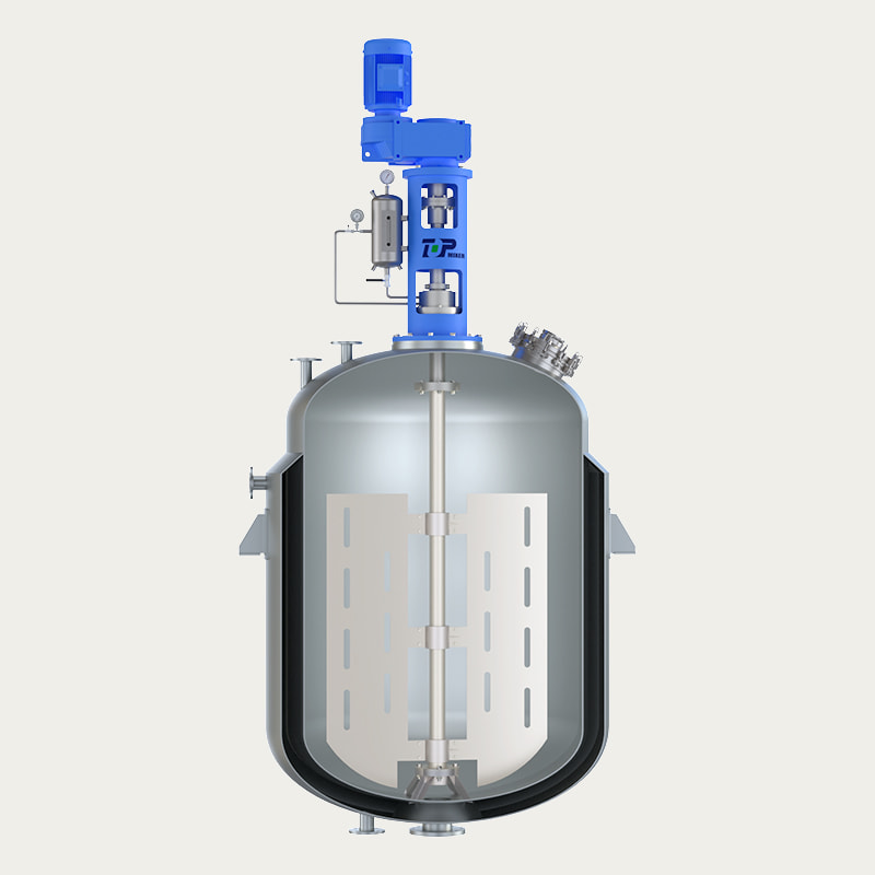
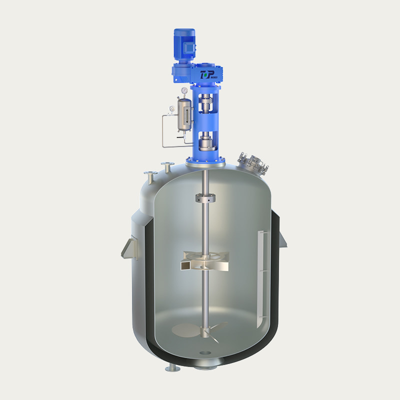
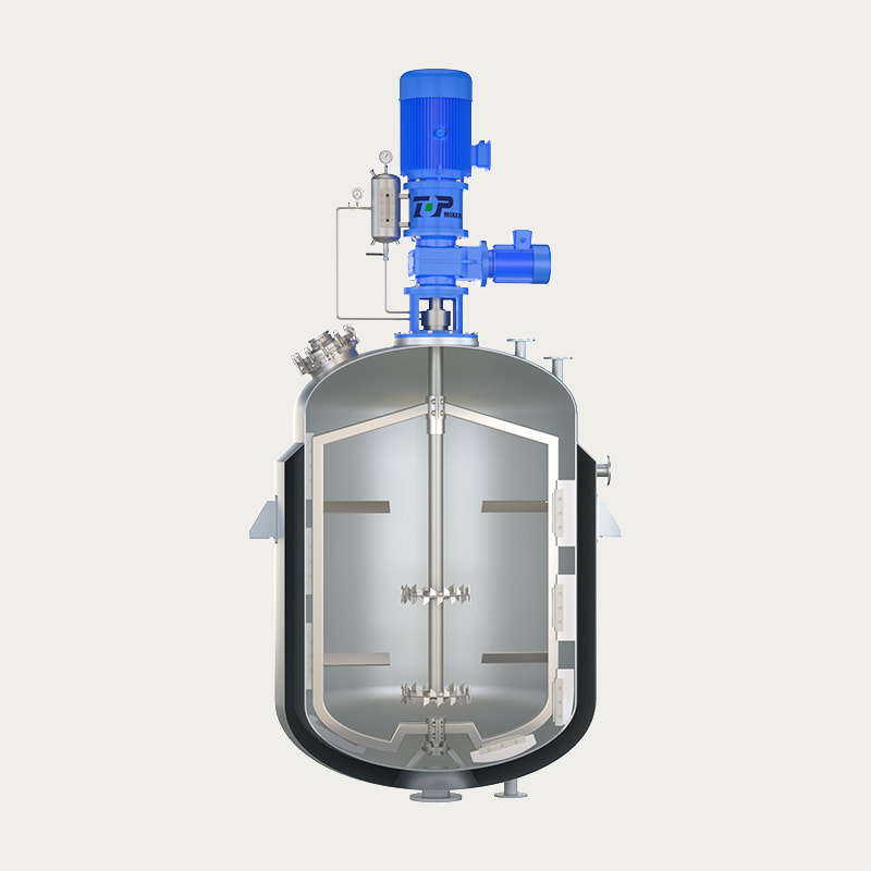
A 상단 입구 믹서는 탱크 또는 용기 상단의 개구부를 통해 장착된 교반기 어셈블리입니다. , 수직 샤프트가 공정 유체로 흘러 들어가고 하나 이상의 임펠러가 액체에 잠겨 있습니다. 구동 모터와 기어 감속기는 탱크 지붕 위나 지지대 위에 위치하여 측면이나 바닥이 아닌 위에서 샤프트를 회전시킵니다. 많은 조달 문서와 기계 데이터 시트에서는 동일한 장비에 상단 공급 혼합기라는 라벨이 붙어 있습니다. 이는 임펠러가 아래의 내용물을 혼합하는 동안 재료, 분말 또는 첨가제 흐름이 상단에서 용기로 들어가는 방식을 강조하는 용어입니다.
교반 구성을 비교하는 엔지니어의 경우 짧은 대답은 다음과 같습니다. 일반적으로 상단 입구 믹서는 탱크가 수천 리터 이상을 담을 때, 프로세스가 샤프트를 따라 두 개 이상의 임펠러 단계를 요구할 때, 다른 노즐이나 세척 장비를 위해 탱크 바닥에 완전히 접근해야 할 때, 또는 유체 점도와 고형물 로딩이 배치 사이클 동안 광범위한 범위에 걸쳐 달라질 때를 지정하는 구성입니다. 측면 입구 및 하단 입구 믹서는 더 좁은 적용 범위에서 여전히 유용하지만 상단 입구 및 상단 공급 제품군은 일반 산업용 혼합, 저장 탱크 혼합 및 반응기 교반 작업에서 가장 큰 부분을 차지합니다.
아래 섹션에서는 엔지니어가 화학 탱크, 폐수조, 식품 배치 용기 또는 대량 물 저장 탱크에 대한 상단 입구 믹서 사양을 마무리하기 전에 일반적으로 필요한 크기 조정 논리, 임펠러 선택, 재료 선택, 장착 관행 및 유지 관리 계획을 안내합니다.
탑엔트리 믹서, 탑피드 믹서 및 관련 용어 설명
혼합 장비에 대한 조달 서류 작업에는 여러 가지 중복되는 용어가 사용되며, 프로젝트를 처음 접하는 엔지니어는 그렇지 않은 경우에도 다른 기계를 참조한다고 가정하는 경우가 있습니다. 아래 표에는 기계 도면, 입찰 문서 및 유지 관리 매뉴얼 전반에 걸쳐 용어가 일반적으로 어떻게 적용되는지 요약되어 있습니다.
| 기간 | 일반적으로 의미하는 것 | 일반적인 사용 상황 |
|---|---|---|
| 탑엔트리 믹서 | 탱크 상단, 샤프트 및 아래쪽으로 연장되는 임펠러를 통해 장착된 교반기 | 화학, 물, 식품, 바이오매스 처리 탱크 |
| 탑피드 믹서 | 재료가 위에서 용기로 공급될 때 종종 사용되는 동일한 상단 장착 구성 | 분말 및 슬러리 혼합, 배치 탱크 사양 |
| 상단 장착형 교반기 | 동일한 장비군에 대한 대체 표현 | 기계 도면 및 엔지니어링 데이터 시트 |
| 상단 장착형 믹서 | 탑엔트리와 탑피드 구성을 함께 다루는 일반적인 설명 용어 | 플랜트 배치도 및 유지보수 매뉴얼 |
실제로 구매 엔지니어는 동일한 견적 요청 내에서 네 가지 용어가 모두 거의 같은 의미로 사용되는 것을 볼 수 있습니다. 라벨보다 더 중요한 것은 샤프트 길이, 임펠러 단계, 씰 유형 및 장착 플랜지 등급과 같은 기본 기계적 세부 사항입니다. 이 모든 내용은 다음 섹션에서 다룹니다.
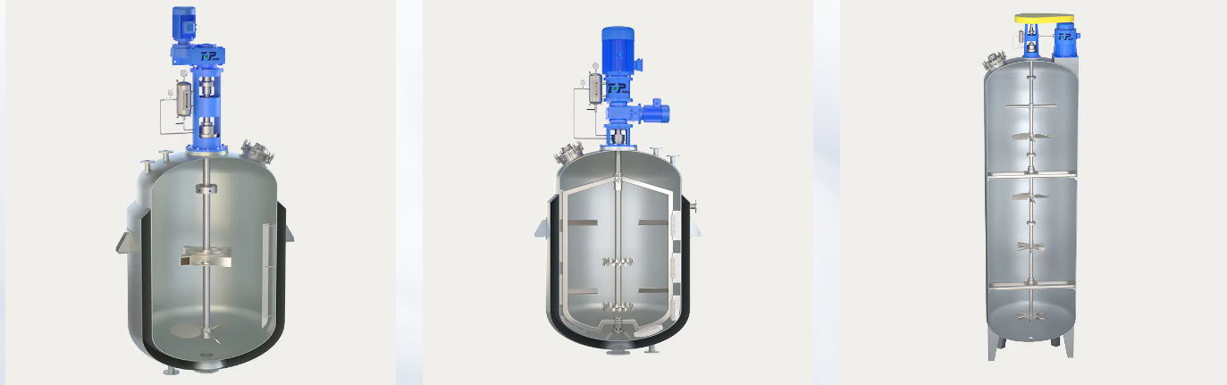
산업용 탑 엔트리 믹서 작동 방식: 핵심 구성 요소
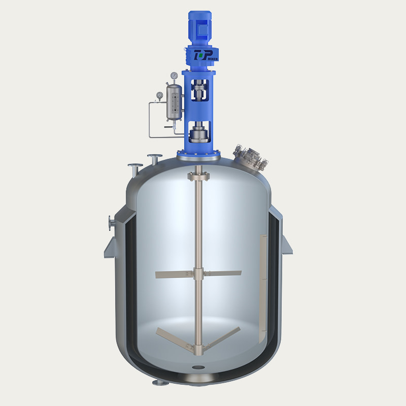
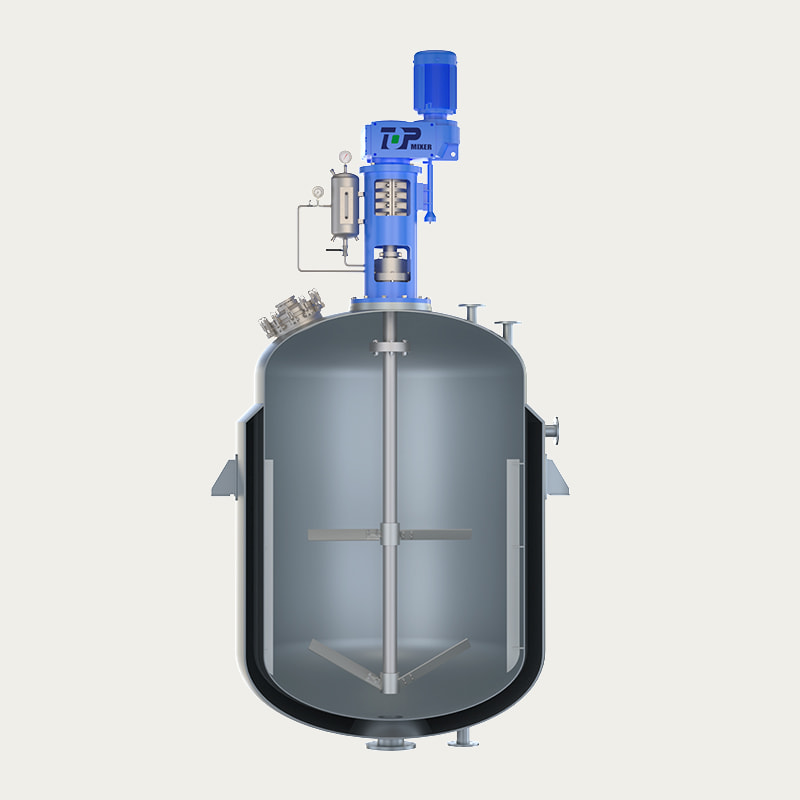
산업용 상단 입구 믹서는 거의 모든 크기와 응용 분야에서 반복되는 작은 구성 요소 세트로 제작되었습니다. 각 부품을 이해하면 엔지니어는 기계 데이터 시트를 빠르게 읽고 프로세스 요구 사항과 제안된 하드웨어 간의 불일치를 찾아내는 데 도움이 됩니다.
모터 및 기어 감속기
모터는 회전 동력을 공급하며, 공정 혼합에는 일반적으로 표준 모터가 생성하는 것보다 훨씬 낮은 샤프트 속도가 필요하기 때문에 기어 감속기는 토크를 배가시키면서 속도를 낮춥니다. 감속기 선택은 전체 조립에서 가장 중요한 결정 중 하나입니다. 왜냐하면 원시 마력이 아닌 토크가 실제로 점성 또는 고체가 함유된 유체를 움직이는 것이기 때문입니다.
믹서 샤프트 및 커플링
샤프트는 감속기에서 탱크 상단을 통해 유체로 토크를 전달합니다. 샤프트 길이, 직경 및 지지 베어링 수는 모두 액체 깊이와 하중을 받는 샤프트의 자연 휩 빈도에 따라 달라집니다. 높은 탱크의 긴 샤프트에는 작동 속도 근처의 공진을 피하기 위해 중간 안정 베어링이 필요한 경우가 많습니다.
임펠러 구성
임펠러 선택은 혼합 목표와 유체 유변학에 따라 달라집니다. 일반적인 유형은 다음과 같습니다.
- 일반 혼합 및 적당한 고형물 현탁을 위한 피치 블레이드 터빈
- 저점도에서 중간 점도 유체의 에너지 효율적인 벌크 흐름을 위한 수중익 임펠러
- 가스 분산 및 더 높은 전단 작업을 위한 플랫 블레이드 또는 Rushton 스타일 터빈
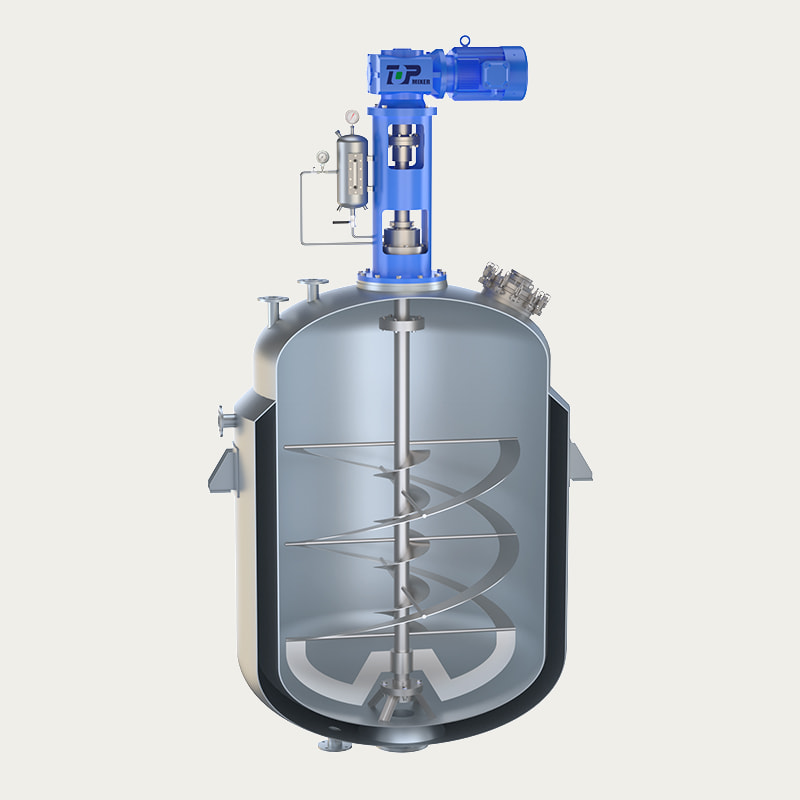
- 유체가 벽에서 거의 떨어지지 않는 고점도 탱크 믹서 서비스용 앵커 및 나선형 리본 임펠러
장착 플랜지 및 샤프트 씰
장착 플랜지는 믹서의 전체 중량과 굽힘 모멘트를 탱크 구조로 전달하므로 플랜지 등급과 볼트 패턴은 믹서 부하와 탱크 지붕 설계 모두와 일치해야 합니다. 간단한 립 씰, 스터핑 박스 또는 기계적 씰 등의 샤프트 씰은 공정 유체를 억제하고 개방형 탱크의 외부 오염을 방지합니다.
올바른 상단 입구 믹서 선택: 주요 엔지니어링 매개변수
견적을 요청하기 전에 엔지니어는 일반적으로 짧은 프로세스 매개변수 목록을 수집합니다. 탱크 형상, 유체 점도, 비중 및 고형물 함량이 함께 상단 입구 믹서가 전달해야 하는 토크와 출력을 결정합니다. , 그중 하나를 건너뛰면 소형 또는 대형 기계가 생성되는 경향이 있습니다.
| 매개변수 | 일반적인 범위 | 엔지니어링 고려 사항 |
|---|---|---|
| 탱크 직경 | 1m ~ 12m | 임펠러 직경 비율 및 샤프트 길이 설정 |
| 액체 깊이 | 탱크 직경의 0.8~1.5배 | 필요한 임펠러 단계 수에 영향을 미칩니다. |
| 유체 점도 | 1cP ~ 50,000cP 이상 | 임펠러 스타일 및 혼합 속도 범위 결정 |
| 비중 | 0.6~1.9 | 토크 및 전력 계산에 직접 반영 |
| 고체 함량 | 슬러리 중량의 경우 최대 40% | 임펠러 간극 및 마모 허용량에 영향을 미칩니다. |
| 토크 요구 사항 | 50Nm ~ 20,000Nm 이상 | 기어 감속기 프레임 및 출력 등급을 구동합니다. |
탱크 용량이 증가함에 따라 필요한 모터 출력도 함께 증가하지만 직선으로 증가하지는 않습니다. 대형 선박은 일반적으로 비례적으로 더 높은 토크와 함께 더 낮은 샤프트 속도로 작동하기 때문입니다. 아래 차트는 탱크 용량에 따라 상단 입구 믹서 또는 상단 공급 믹서의 범위를 지정할 때 엔지니어가 참조하는 일반적인 모터 전력 대역을 보여줍니다.
그림 1: 탱크 부피에 따른 상단 입구 믹서 모터 전력의 일반 기준 대역. 실제 출력은 점도, 비중 및 임펠러 선택에 따라 달라집니다.
고점도 탱크 믹서의 유체 점도에 혼합 속도 맞추기
샤프트 속도와 유체 점도는 반대 방향으로 움직입니다. 묽은 물 같은 유체는 상대적으로 높은 RPM에서 효과적으로 혼합될 수 있는 반면, 두꺼운 페이스트와 슬러리에는 구동 트레인의 정지 또는 샤프트의 과부하를 방지하기 위해 훨씬 더 많은 토크와 함께 낮은 RPM에서 작동하는 고점도 탱크 믹서가 필요합니다. 점성 유체를 너무 빠르게 작동하면 혼합 품질이 향상되지 않고 에너지를 낭비하고 전단 응력이 증가하는 반면, 묽은 유체를 너무 느리게 작동하면 배치 사이클 시간이 이익 없이 연장됩니다.
그림 2: 일반적으로 점도가 증가하면 속도가 떨어지므로 속도가 아닌 토크가 두꺼운 유체의 제한 설계 요소가 됩니다.
2개의 무차원 숫자는 혼합 공학 실습에서 이러한 관계를 안내합니다. 즉, 관성력을 탱크의 점성력과 비교하는 혼합 레이놀즈 수와 임펠러 형상을 주어진 속도에서 끌어오는 전력과 연결하는 전력 수입니다. 낮은 레이놀즈 수에서는 흐름이 층류로 유지되는 경향이 있습니다. 즉, 탱크 벽 가까이에서 작동하는 나선형 리본이나 앵커 임펠러가 정체 구역을 그대로 유지하는 소형 고속 터빈보다 훨씬 더 효과적이라는 의미입니다.
탑 엔트리 및 탑 피드 믹서의 산업 응용
탑 엔트리 및 탑 피드 믹서는 광범위한 공정 산업에 걸쳐 나타납니다. 기본 장착 구성이 동일하게 유지되더라도 특정 임펠러, 씰 및 재료 선택은 적용 분야마다 다릅니다.
화학 탱크 블렌딩을 위한 탑 엔트리 믹서
화학 처리에서 화학물질 탱크 작업을 위한 상단 입구 믹서는 일반적으로 시약 혼합, pH 조정 탱크 및 반응 용기를 처리합니다. 많은 화학 물질 흐름이 표준 탄소강 습식 부품에 대해 공격적이기 때문에 내부식성과 밀봉 무결성이 원시 전력보다 더 중요한 경향이 있습니다.
폐수 처리용 탑 엔트리 믹서
폐수 처리를 위한 상부 입구 믹서는 일반적으로 처리장의 균등화 탱크, 중화 탱크 및 화학물질 투여 탱크에 설치됩니다. 이러한 장치는 일반적으로 연속적으로 작동하므로 지속적인 사용 시 베어링 및 씰 내구성이 핵심 선택 요소가 됩니다.
슬러지 혼합용 탑 엔트리 믹서
혐기성 소화조 및 농축 탱크는 고형물을 부유 상태로 유지하고 층화를 방지하기 위해 슬러지 혼합을 위해 상단 입구 믹서를 사용합니다. 슬러지 서비스는 보통 적당한 점도와 연마성 고형물을 결합하여 견고한 임펠러 코팅과 더 넓은 샤프트 간격을 선호합니다.
물탱크 보관용 상부 입구 믹서
음용수 및 공정수 저장 시설은 주로 열 성층화를 방지하고 소독제 잔류물을 저장 용량 전체에 고르게 분포시키기 위해 물 탱크 용도로 상단 입구 믹서를 사용합니다. 유체 자체가 물 점도에 가깝기 때문에 여기서 필요한 전력은 일반적으로 적당합니다.
식품 가공용 탑 엔트리 믹서
식품 가공용 최고급 믹서는 일반적으로 위생적인 디자인, 매끄러운 내부 표면, 빈번한 세척 주기를 견딜 수 있는 재료를 우선시합니다. 이 부문에서는 배치 일관성과 부드러운 전단 제어가 원시 혼합 강도만큼 중요합니다.
| 신청 | 일반적인 임펠러 | 1차 혼합 목표 |
|---|---|---|
| 화학 탱크 혼합 | 피치 블레이드 터빈 | 균일한 시약 분포 |
| 폐수 균등화 | 수중익 임펠러 | 흐름 혼합 및 고형물 현탁액 |
| 슬러지 소화 | 넓은 피치 블레이드 또는 앵커 | 계층화 및 정착 방지 |
| 물탱크 보관 | 저속 축방향 임펠러 | 열 성층화 방지 |
| 식품 일괄 처리 | 위생적인 피치 또는 앵커 블레이드 | 부드럽고 일관된 블렌딩 |
재질 및 인클로저 선택: 스테인리스강 및 방폭 옵션
스테인레스 스틸 탑 엔트리 믹서
스테인레스 스틸 상단 입구 믹서는 일반적으로 공정 유체가 부식성이거나 염분이거나 위생적인 표면 마감이 필요할 때마다 지정됩니다. 식품 및 음료, 의약품 중간체, 정밀 화학 처리 라인은 표면 품질 저하 없이 잦은 세척 및 현장 청소 주기를 견딜 수 있기 때문에 스테인리스 습식 부품을 선호합니다.
방폭형 탑 엔트리 믹서
방폭 상단 입구 믹서는 믹서가 가연성 용제, 가연성 먼지 또는 기타 위험한 대기를 취급하는 구역에서 작동할 때 잠재적인 발화원을 포함하도록 설계된 밀봉된 정격 모터 인클로저를 사용합니다. 인클로저 유형이 모터 프레임 크기와 장착 배열에 영향을 주기 때문에 이러한 프로젝트에 참여하는 엔지니어는 일반적으로 설계 단계 초기에 플랜트의 영역 분류 연구와 인클로저 선택을 조정합니다.
| 특징 | 스테인레스 스틸 | 탄소강 |
|---|---|---|
| 부식 저항 | 산성, 염분 또는 고순도 유체에 적합 | 중립, 비부식성 서비스에 적합 |
| 표면 마감 | 위생적 의무를 위해 광택 처리 또는 부동태화 처리 | 코팅 또는 페인트 마감 |
| 대표적인 분야 | 식품, 의약품 중간체, 정밀화학 | 폐수, 물 저장, 일반 화학물질 혼합 |
| 청소 요구 사항 | Frequent washdown, clean-in-place cycles | Periodic inspection and routine cleaning |
Comparing Mounting Types: Top Entry, Side Entry, and Bottom Entry Mixers
Choosing between mounting types is one of the earliest decisions in a mixing system layout. An industrial top entry mixer generally offers the widest flexibility across tank sizes and process duties, which is why it remains the default choice for most heavy duty industrial mixer specifications, though side entry and bottom entry configurations still fit specific layouts better in some plants.
Figure 3: Relative comparison across five practical factors, scored on a general five-point engineering reference scale rather than a fixed standard.
Side entry mixers can suit very large open tanks where a top entry shaft would need to be impractically long, and bottom entry mixers occasionally fit tight headroom situations. Even so, a top mounted agitator arrangement usually wins out once maintenance access and sealing reliability are weighed alongside mixing performance, since the drive components remain above the liquid line and are reachable without draining the vessel.
Maintenance Planning and Reliability for Top Mounted Mixers
Reliability planning for a top mounted mixer generally centers on three wear points: the shaft seal, the gear reducer lubrication, and the impeller attachment hardware. Seal condition is usually the first thing to check during a scheduled inspection , since a degrading seal often shows up as fluid seepage around the mounting flange well before any drive train symptoms appear.
Figure 4: General inspection interval reference points, adjusted in practice based on duty cycle, fluid abrasiveness, and continuous versus intermittent operation.
Continuous duty in wastewater or sludge service tends to shorten these intervals compared with intermittent batch tanks, and abrasive solids content accelerates impeller and shaft coating wear regardless of mounting type. Recording vibration trends and gearbox oil condition over time gives an early warning well before a seal or bearing actually fails.
Installation Guidelines for Heavy Duty Industrial Mixer Systems
Installation quality has a direct effect on long-term reliability for any heavy duty industrial mixer, and most field issues trace back to one of the following steps being rushed or skipped during commissioning.
- Confirm the tank roof or support structure can carry the full static weight plus the bending moment generated during operation, not just the mixer's dry weight.
- Verify shaft alignment between the gear reducer output and the mixer shaft coupling before the vessel is filled, since misalignment under load is far harder to correct later.
- Check impeller clearance from the tank wall and bottom against the drawing tolerance, particularly on vessels with internal baffles or coils.
- Torque all mounting flange bolts to the specified sequence and value rather than tightening in a single pass around the flange.
- Run an initial no-load test to confirm rotation direction and check for shaft whip before introducing process fluid.
- Record baseline vibration and current draw readings once the mixer is running under normal process conditions, since these numbers become the reference point for future maintenance checks.
Structural support deserves particular attention on retrofit projects, where an existing tank roof designed for a lighter agitator or no agitator at all may need reinforcement before a larger top mounted mixer can be installed safely.
Working With a Top Entry Mixer Manufacturer
Selecting a top entry mixer manufacturer involves more than comparing a data sheet against a process requirement. Engineering support during the specification phase, the ability to model non-standard tank geometry, and access to application experience across multiple industries all shape how well the final equipment performs once it reaches the field.
Wuxi Top Mixer Equipment Co., Ltd. is one example of an industrial agitator manufacturer with a dedicated engineering team spanning fluid, powder, and slurry mixing equipment. Established in 2003 with its production base in Wuxi, within the Yangtze River Delta industrial region, the company organizes its work across several application divisions, including powder and slurry mixing, biomass energy and environmental protection, food and pharmaceutical intermediate processing, and fine chemical mixing. This kind of divisional structure is common among manufacturers that serve a broad customer base, since impeller geometry, seal type, and material selection differ substantially between a food batching tank and a fine chemical reactor.
When engineers evaluate a top entry mixer manufacturer, a few practical questions tend to surface early in the conversation: can the manufacturer model shaft critical speed for a non-standard tank height, can they source impeller materials matched to an unusual fluid chemistry, and can they support commissioning and troubleshooting once the unit is installed. Manufacturers with experience across chemical, water treatment, food, and biomass sectors generally bring a wider frame of reference to these questions than a supplier working from a single catalog configuration.
Frequently Asked Questions
-
Q1: What is a top entry mixer
A: It is an agitator mounted through the top of a tank, with the shaft and impeller extending downward into the process fluid while the motor and reducer remain above the vessel.
-
Q2: How does a top entry mixer work
A: The motor drives a gear reducer that lowers speed and raises torque, turning a vertical shaft connected to one or more impellers that create flow patterns inside the tank to blend or suspend the contents.
-
Q3: What is a top-feed mixer
A: The term describes the same top-mounted configuration, often used when the process involves feeding powder, additive, or liquid streams into the vessel from above while the impeller blends the mixture.
-
Q4: What is an industrial agitator
A: It is a general term for equipment that creates motion inside a tank or vessel to blend fluids, suspend solids, or maintain uniform temperature and composition throughout a process batch.
-
Q5: What is tank agitation
A: Tank agitation refers to the mechanical process of creating flow inside a vessel, typically through a rotating impeller, to achieve blending, suspension, heat transfer, or reaction uniformity.
-
Q6: How do I choose the right top entry mixer for my tank
A: Start with tank geometry, fluid viscosity, specific gravity, and solids content, then match torque and impeller type to those parameters before selecting motor power and seal configuration.
-
Q7: What is the difference between a top entry mixer and a side entry mixer
A: A top entry mixer mounts through the tank top with the drive above the liquid line, while a side entry mixer mounts through the tank wall near the bottom, which suits certain large open tank layouts.
-
Q8: Can a top entry mixer handle high viscosity fluids
A: Yes, with the right impeller such as an anchor or helical ribbon design and a gear reducer sized for low speed and high torque, a high viscosity tank mixer configuration can handle thick fluids effectively.
-
Q9: What industries use top entry mixers
A: Chemical processing, wastewater treatment, sludge digestion, water storage, food and beverage processing, and biomass energy facilities all commonly use top entry and top-feed mixers.
-
Q10: How often should a top entry mixer be serviced
A: Inspection intervals vary with duty cycle and fluid abrasiveness, but many continuous duty units are checked on a roughly six to twelve month cycle, with seal and gearbox oil condition as primary checkpoints.
-
Q11: Does a top entry mixer manufacturer offer custom designs
A: Many manufacturers, including Wuxi Top Mixer Equipment Co., Ltd., work with engineers to model non-standard tank geometry and adjust shaft length, impeller type, and seal configuration around the specific process.
-
Q12: What is the role of the gear reducer in a top mounted agitator
A: The gear reducer converts motor speed into the lower shaft speed and higher torque that most mixing duties require, and its rating largely determines how much load the mixer can handle in service.


- No. 118, Chuangye Road, Jieshou Town, Gaoyou City, Yangzhou, Jiangsu Province, China
- [email protected]
- Landline: +86-0510-83383966 +86-0510-83390667
- Telphone: +86-0510-83390667
- Mr. Chen: +86-18061519769 Mr. Xu: +86-13706183972
- Mr. Lu: +86-18915337056
- Product Link
- Top-Entry Mixer
- Bottom-Entry Mixer
- Side-Entry Mixer
- SIGN UP
- Sign up to be the first to find out the latest news from Top Intelligent Technology
- Subscribe

