



How Does a Bottom Entry Mixer Improve Tank Mixing Efficiency?
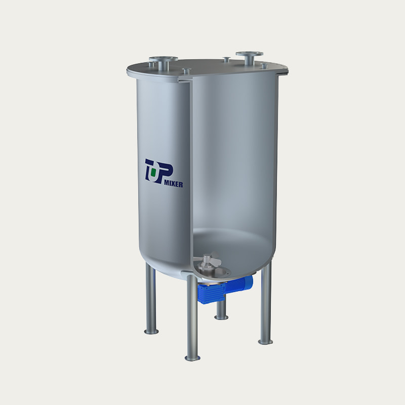
A 하단 입구 믹서 용기의 가장 낮은 지점에서 직접 교반을 제공하고, 데드존을 제거하고, 에너지 낭비를 줄이고, 상단 입구 대안보다 훨씬 짧은 시간에 균일한 혼합을 달성함으로써 탱크 혼합 효율성을 향상시킵니다. 탱크 바닥 아래에 설치되며 직접 구동 모터로 구동되는 혼합 탱크용 하단 입구 믹서 기존의 측면 입구 또는 상단 입구 구성에 비해 20~35%의 에너지 절감 효과가 있는 것으로 측정되었습니다.
이 가이드에서는 제약, 식품 생산, 정밀 화학 및 환경 처리 분야의 엔지니어가 일관되게 하단 장착형 교반기 저-중점도 공정에 선호되는 혼합 솔루션입니다.
하단 피드 믹서 성능의 핵심 엔지니어링 원리
A의 근본적인 장점 하단 공급 믹서 유체 역학에 있습니다. 임펠러가 탱크 바닥에서 회전하면 전체 액체 기둥을 아래에서 위로 순환시키는 수직 펌핑 작용이 발생합니다. 이 대류 루프는 임펠러 영역을 지속적으로 새로 고치고 열 또는 농도 구배가 안정화되는 것을 방지하며 충전 수준에 관계없이 용기 전체에 기계적 에너지를 고르게 분배합니다.
기존의 상단 입구 교반기는 임펠러 위의 유체 기둥의 정수압을 극복해야 하므로 더 큰 모터와 더 견고한 샤프트 어셈블리가 필요합니다. 에이 고점도용 하단 입구 교반기 애플리케이션은 이 제약 조건을 완전히 우회합니다. 샤프트 길이가 최소화되고 굽힘 모멘트가 감소하며 긴 샤프트를 괴롭히는 중요한 속도 문제가 크게 제거됩니다. 독립적인 마찰학 연구에 따르면 샤프트 구성이 짧을수록 유사한 작동 주기에 비해 기계적 씰 마모가 최대 40% 감소하는 것으로 확인되었습니다.
또한 직접 구동 모터 배열은 다양한 구성에서 중간 기어박스를 제거하여 일반적으로 기어 구동 시스템에서 입력 에너지의 8~15%를 차지하는 전송 손실을 줄입니다. 연간 6,000~8,000시간 연속 작동의 경우 이는 전기 비용과 예정된 유지 관리 간격 모두에서 측정 가능한 감소를 의미합니다.
그림 1: 믹서 구성 전반에 걸친 비교 에너지 전송 손실. 직접 구동 하단 진입형 시스템은 약 12%로 가장 낮은 기생 손실을 달성합니다.
그림 1과 같이 다이렉트 드라이브 하단 입구 믹서 디자인 기어 구동식 상단 엔트리 시스템의 35%에 비해 에너지 전송 손실을 약 12%로 줄입니다. 이러한 차이는 고강도 작업에 매우 중요합니다. 생산 연도 동안의 복합적인 효과는 모터 정격 및 연간 작동 시간에 따라 믹서 장치당 절약된 수만 킬로와트시를 나타낼 수 있습니다.
혼합 균일성: 하단 입구 구조가 데드존을 제거하는 방법
효과적인 혼합을 위한 유체 속도가 임계값 아래로 떨어지는 정체 영역인 데드존(Dead Zone)은 혼합 균일성의 주요 적입니다. 충전 수준이 낮은 상부 입구 탱크에서는 임펠러가 완전히 잠기지 않아 생산적인 교반 대신 표면 소용돌이와 공기 연행이 발생할 수 있습니다. 측면 진입 구성에서 임펠러 제트는 탱크 단면의 일부에만 도달하므로 모서리와 하단 중앙 영역이 제대로 교반되지 않습니다.
제대로 설계된 탱크 바닥 믹서 시스템 임펠러를 탱크 베이스의 기하학적 중심에 배치합니다. 결과적으로 방사상 및 축류 흐름 패턴은 용기의 모든 영역에 동시에 도달합니다. 직경 대 높이 비율이 1:1.5인 원통형 탱크에서 수행된 전산유체역학(CFD) 연구는 바닥 입구 구성이 95% 체적 혼합 효율 60~90초 이내에 작동하는 반면, 동일한 전원 입력에서 작동하는 동등한 최상위 시스템은 비슷한 균일성에 도달하는 데 150~220초가 필요합니다.
그림 2: 동일한 전력 입력에서 세 가지 믹서 구성에 대한 시간 경과에 따른 균질성 달성률. 하단 입구 형상은 상단 입구 대안보다 약 60% 더 빠르게 95% 균일성에 도달합니다.
그림 2의 데이터는 여러 산업 실험에서 확인된 일관된 패턴을 보여줍니다. 즉, 하단 투입 시스템은 배치 간 편차가 적고 공정 준비 균질성에 더 빠르게 도달합니다. 이러한 속도 이점은 혼합 시간의 변화가 분석 결과에 직접적인 영향을 미치는 의약품 용해 테스트나 지연된 균질화가 질감과 보관 안정성을 손상시킬 수 있는 식품 유화와 같이 시간에 민감한 작업에서 특히 중요합니다.
위생 설계 표준: 위생적인 하단 입구 믹서 구성이 중요한 이유
GMP(Good Manufacturing Practice), FDA, EHEDG 또는 3-A 위생 표준에 따라 운영되는 산업에서는 철저하게 세척, 검사 및 검증할 수 있는 혼합 장비가 필요합니다. 에이 위생적인 하단 입구 믹서 기존의 최고급 장비에서는 사용할 수 없는 여러 가지 설계 기능을 통해 이러한 요구 사항을 충족합니다.
첫째, 샤프트가 액체 표면 아래에서 들어가므로 탱크 내부에 머리 위의 기계 구성 요소가 전혀 없는 상태로 유지됩니다. 이는 위에 장착된 베어링으로 인한 윤활유 오염 위험을 제거합니다. 이는 모든 제품 접촉 환경에서 중요한 문제입니다. 둘째, 젖은 구성 요소 스테인레스 스틸 하단 입구 믹서 일반적으로 Ra ≤ 0.8 µm 내부 표면 마감 처리된 316L 또는 304L 오스테나이트 스테인리스강으로 제작되어 대부분의 국제 위생 규정의 거칠기 요구 사항을 충족합니다. 셋째, 기계적 밀봉 설계는 압력 등급 CIP/SIP 절차를 완벽하게 준수하는 멸균 배리어 유체를 사용하는 단일 또는 이중 밀봉으로 구성될 수 있습니다.
위생 규정 준수 기능 비교
| 특징 | 하단 입구 (Hygienic) | 탑 엔트리 (Standard) | 측면 진입 |
|---|---|---|---|
| 간접비 오염 위험 | 없음 | 현재 | 낮음 |
| CIP/SIP 호환성 | 전체 | 부분 | 부분 |
| 내부 표면 Ra(μm) | ≤ 0.8 | 1.6–3.2 | 1.6–3.2 |
| 씰 옵션 | 싱글 / 더블 / 메마른 | 싱글 / 더블 | 싱글 / 립 |
| 막다른 위험 | 최소 | 보통 | 높음 |
잔여 제품이나 세척액이 축적될 수 있는 유체 트랩인 데드 레그(Dead-leg) 제거는 운영상 가장 중요한 장점 중 하나입니다. 위생적인 바닥 장착형 믹서 플랫폼. 상단 또는 측면 진입 시스템의 데드 레그는 수동 청소를 위해 분해가 필요한 경우가 많으며 각 생산 주기에 노동 시간과 검증 복잡성이 추가됩니다. 스프레이 볼 CIP 프로토콜에 따라 검증된 하단 입구 설계는 많은 탱크 구조에서 이 단계를 완전히 제거합니다.
산업 전반에 걸친 애플리케이션 성능: 벤치마킹 데이터
다재다능함 하단 입구 믹서 플랫폼은 광범위한 산업 상황에서 시연됩니다. 핵심 엔지니어링은 일관성을 유지하면서 임펠러 선택, 씰 사양 및 모터 크기는 각 부문의 특정 점도 범위, 전단 감도 및 규제 환경에 맞게 조정됩니다.
그림 3: 상단 또는 측면 입구 시스템에서 하단 입구 믹서 구성으로 전환한 후 시설에서 보고한 측정된 프로세스 효율성 개선. 생명공학 및 제약 부문은 혼합 균일성과 오염 제어에 대한 민감성으로 인해 가장 큰 이점을 얻습니다.
생명공학 및 발효 응용 분야는 통제된 비교에서 최대 79%까지 기록된 가장 높은 효율성 향상을 보여줍니다. 왜냐하면 세포 배양 공정은 특히 전단 응력과 용존 산소 분포 모두에 민감하기 때문입니다. 저전단 하단 입구 믹서 디자인 해양형 또는 수중익 임펠러를 사용하면 호기성 배양에 필요한 기액 물질 전달 계수를 달성하면서 세포 생존성을 유지합니다. 대조적으로, 상용 화학 탱크에 일반적으로 사용되는 고전단 상단 입구 프로펠러는 이러한 응용 분야에 부적절합니다.
에 대한 식품 산업용 하단 입구 믹서 , 구체적인 이점은 다음과 같습니다.
- 제품 라인별 전용 씰 구성을 통한 알레르기 유발 물질 분리
- 대형 저장/혼합 탱크 전반에 걸쳐 ±0.5°C 이내의 온도 균일성
- 고당분 또는 유제품 응용 분야에서 지방 분리 및 결정 핵 생성 방지
- NSF/ANSI 51 또는 EHEDG 준수 습식 재료 사양을 표준으로 제공
고점도 처리: 하단 입구 교반기의 차이점
공정 유체 점도가 약 500mPa·s 이상으로 증가하면 레이놀즈 수가 층류 또는 천이 흐름 영역으로 떨어지며 기존 임펠러 설계는 의미 있는 대량 유체 이동을 생성하는 능력을 상실합니다. 이곳은 고점도용 하단 입구 교반기 앵커, 게이트 또는 나선형 리본 임펠러가 장착된 구성은 결정적인 이점을 보여줍니다.
임펠러는 탱크 베이스에 위치하므로 시스템의 가장 높은 정수압 지점에서 작동하여 유체 변위를 위한 추가 구동력을 제공합니다. 또한 짧은 샤프트 구성을 통해 믹서는 샤프트 편향 없이 더 높은 토크 출력을 유지할 수 있어 더 넓은 임펠러 직경(일부 나선형 리본 설계에서 탱크 직경의 최대 85~90%)이 가능합니다. 이는 동일한 굽힘 모멘트 제약 조건에서 작동하는 긴 상단 입구 샤프트로는 물리적으로 불가능합니다.
그림 4: 일반적인 산업용 믹서 구성에 대한 유효 점도 작동 범위. 하단 입구 나선형 리본 디자인은 표준 상단 입구 프로펠러 범위의 5배인 250,000mPa·s까지 공정 능력을 확장하여 페이스트, 젤 및 농축 폴리머 솔루션에 사용할 수 있습니다.
이 확장된 점도 범위의 실제적인 의미는 단일 산업용 하단 공급 믹서 플랫폼은 추가 장비 없이도 시설 포트폴리오 전반에 걸쳐 여러 제품 등급을 처리할 수 있는 경우가 많습니다. 저점도 헹굼 용액(10mPa·s)과 고점도 젤(80,000mPa·s)을 모두 생산하는 시설은 적절하게 지정된 하단 입구 장치를 모두 사용할 수 있는 반면, 유사한 상단 입구 설정에는 각 응용 분야에 대해 근본적으로 다른 장비 범주가 필요합니다.
레이더 성능 프로필: 하단 진입과 대체 기술
플랜트 엔지니어가 혼합 장비를 지정할 때 평가하는 주요 성능 차원에 대한 전체적인 비교를 제공하기 위해 아래 레이더 차트는 에너지 효율성, 혼합 균일성, 위생 규정 준수, 점도 범위, 유지 관리 간격 및 설치 유연성의 6가지 기준에 따라 각 구성의 점수를 매깁니다. 점수는 공개된 엔지니어링 데이터 및 업계 관행을 기반으로 1~10점 척도로 정규화됩니다.
그림 5: 6가지 엔지니어링 기준(등급 1~10)에 걸쳐 표준화된 성능 레이더. 하단 입구 구성은 위생 규정 준수, 에너지 효율성 및 유지 관리 간격에서 가장 강력한 차별화를 통해 프로세스에 중요한 모든 차원에서 일관되게 높은 점수를 받았습니다.
The radar profile confirms that the bottom-entry configuration is not simply better in one dimension — it delivers a consistently superior performance profile across all major evaluation criteria. The only area where top-entry systems offer marginal advantage is installation flexibility for very large tanks (above 500 m³), where the structural requirements of a bottom flange connection can increase civil engineering costs. For tanks below this threshold, bottom-entry is the preferred choice for most process environments.
Maintenance Lifecycle and Operational Cost Analysis
Total cost of ownership is rarely determined by the initial purchase price. For industrial mixing equipment, the dominant cost drivers over a 10–15 year service life are mechanical seal replacement, bearing maintenance, shaft alignment, and unplanned downtime. The 하단 장착형 교반기 architecture addresses each of these systematically.
Mechanical seal life in bottom-entry applications typically extends to 18,000–24,000 operating hours before scheduled replacement, compared to 8,000–14,000 hours in comparable top-entry configurations operating under equivalent conditions. The primary reason is reduced shaft deflection: with shorter shafts and lower bending moments, seal faces maintain more consistent contact pressure, reducing wear rate by 35–50%. For a facility running three shifts, this difference translates to roughly 4–6 additional years of service life per seal assembly.
Figure 6: Cumulative maintenance cost index over a 10-year service period. Bottom-entry systems accumulate roughly 55% of the total maintenance expenditure of comparable top-entry units, primarily due to extended seal life and reduced bearing replacement frequency.
Beyond seal replacement, the 산업용 하단 공급 믹서 platform benefits from simpler alignment procedures. Because the shaft is short and the motor mounts directly to the tank flange, there are no flexible couplings, steady bearings, or intermediate support brackets to align during reinstallation. Maintenance crews with standard training can complete a seal change in 2–4 hours, compared to 6–12 hours for a long-shaft top-entry agitator requiring full disassembly and realignment after servicing.
Installation Considerations for Bottom Entry Mixer Design
Successful deployment of a 하단 입구 믹서 디자인 begins at the tank design stage. Retrofitting an existing tank is possible but requires careful evaluation of the tank base structural integrity, nozzle positioning, and drainage requirements. For new tank installations, the mixer flange should be specified concurrently with the vessel design to ensure adequate clearance between the impeller and the tank base (typically 0.3–0.5× impeller diameter) and correct positioning relative to baffles or internal coils.
Key engineering parameters to define at the specification stage include:
- Tank geometry: Diameter-to-height ratio affects the number of impeller stages required for full-column mixing.
- Process fluid properties: Viscosity, density, and shear sensitivity determine impeller type, tip speed, and motor sizing.
- Operating pressure and temperature: Pressure-rated seal assemblies and material selection depend on maximum process conditions.
- Regulatory environment: FDA, GMP, ATEX, or EHEDG certifications dictate specific material and documentation requirements.
- Cleaning regime: CIP spray density and chemical compatibility must be validated against seal and gasket materials.
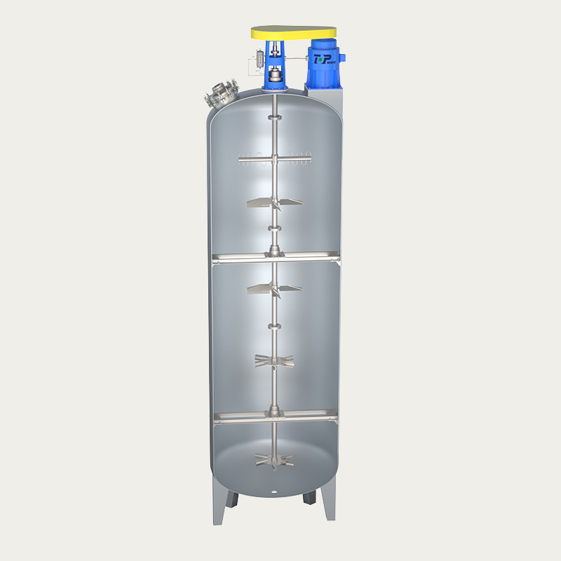
For tanks exceeding 10 m in height, a 탱크 바닥 믹서 시스템 may incorporate a dual-impeller configuration on a single extended shaft, maintaining the short-shaft advantage at the base while extending the mixing influence through the full liquid column. This approach eliminates the stratification risk in tall, narrow vessels without reverting to top-entry geometry.
Frequently Asked Questions
Q1: What viscosity range can a bottom entry mixer handle?
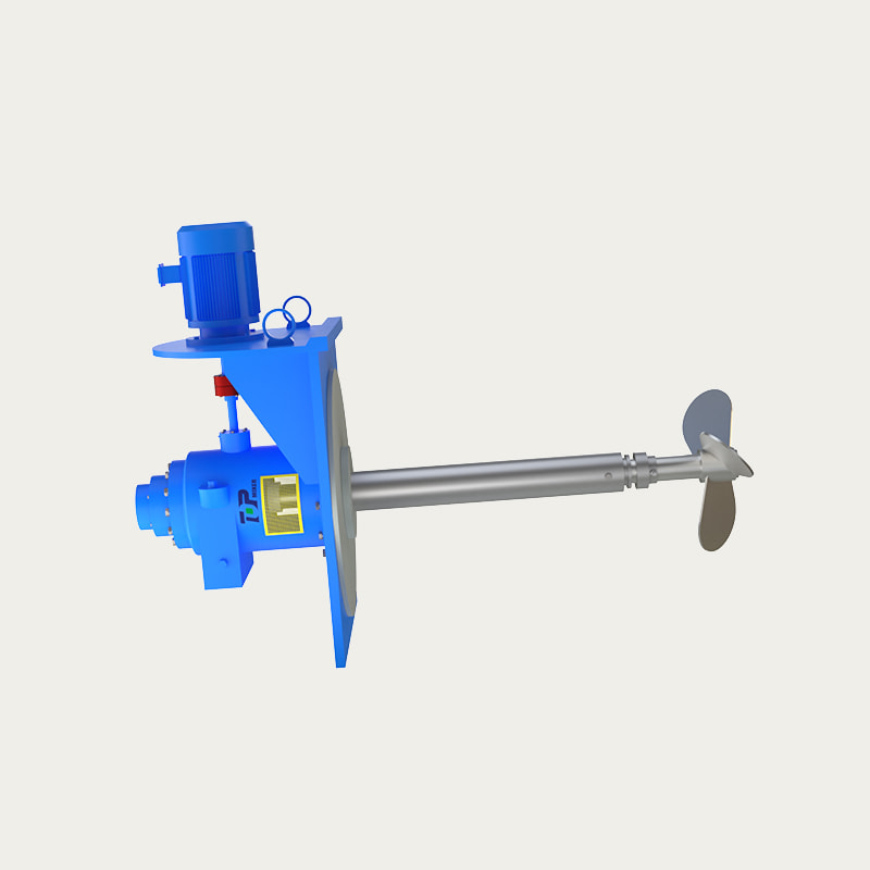
A standard 하단 입구 믹서 with a propeller or hydrofoil impeller is effective up to approximately 5,000–10,000 mPa·s. With anchor or helical ribbon impellers mounted on the bottom-entry platform, operating ranges extend to 200,000–250,000 mPa·s. The specific impeller selection should be confirmed through a process review based on your fluid's measured rheological properties.
Q2: Can a bottom entry mixer be used in pressurized tanks?
Yes. 스테인레스 스틸 하단 입구 믹서 units are available with pressure-rated mechanical seal assemblies suitable for tanks operating up to and beyond 6 bar gauge. Double mechanical seals with sterile barrier fluid are the standard specification for high-pressure or aseptic applications. Vessel nozzle ratings and gasket material selection must be matched to the maximum allowable working pressure.
Q3: How is a bottom entry mixer cleaned — does it support CIP?
A properly designed 위생적인 바닥 장착형 믹서 fully supports CIP (Clean-in-Place) and SIP (Sterilize-in-Place) procedures. The wetted components — shaft, impeller, and seal housing — are manufactured to Ra ≤ 0.8 µm surface finish to prevent biofilm adhesion. CIP validation protocols typically include spray-ball coverage mapping and rinse sampling to confirm cleaning efficacy without disassembly.
Q4: Can an existing top-entry mixer tank be retrofitted with a bottom entry unit?
Retrofitting is feasible in many cases, but requires a structural assessment of the tank base to confirm it can support the nozzle flange and mixer weight. The tank must also be taken out of service for nozzle cutting and welding. For tanks currently in continuous production, it may be more practical to integrate the bottom-entry specification into the next scheduled vessel replacement cycle rather than interrupting operations.
Q5: What materials are available for the wetted parts of a bottom entry mixer?
Standard wetted-part material is 316L stainless steel, chosen for its corrosion resistance and compliance with pharmaceutical and food sanitary codes. For highly corrosive media, Hastelloy C-276, duplex stainless steel (2205), or titanium are available. Impeller and shaft surfaces are typically electropolished or mechanically polished to specified Ra values. Material certification (3.1 mill certificates per EN 10204) is provided as standard for regulated industries.
Q6: How does a bottom entry mixer prevent sedimentation in storage tanks?
The upward pumping action generated by the bottom-mounted impeller continuously re-suspends settled particles before they can form compacted sediment layers. Even at low rotational speeds (30–60 RPM), the proximity of the impeller to the tank base creates sufficient fluid shear at the sediment interface to maintain suspension. This operating mode — often called "settling prevention" or "slow agitation" — uses significantly less energy than the mixing intensity required for active dissolution or blending.


- No. 118, Chuangye Road, Jieshou Town, Gaoyou City, Yangzhou, Jiangsu Province, China
- [email protected]
- Landline: +86-0510-83383966 +86-0510-83390667
- Telphone: +86-0510-83390667
- Mr. Chen: +86-18061519769 Mr. Xu: +86-13706183972
- Mr. Lu: +86-18915337056
- Product Link
- Top-Entry Mixer
- Bottom-Entry Mixer
- Side-Entry Mixer
- SIGN UP
- Sign up to be the first to find out the latest news from Top Intelligent Technology
- Subscribe

